- 您现在的位置:买卖IC网 > Sheet目录3880 > PIC12F683-I/MD (Microchip Technology)IC PIC MCU FLASH 2KX14 8DFN
2007 Microchip Technology Inc.
DS41211D-page 119
PIC12F683
15.3
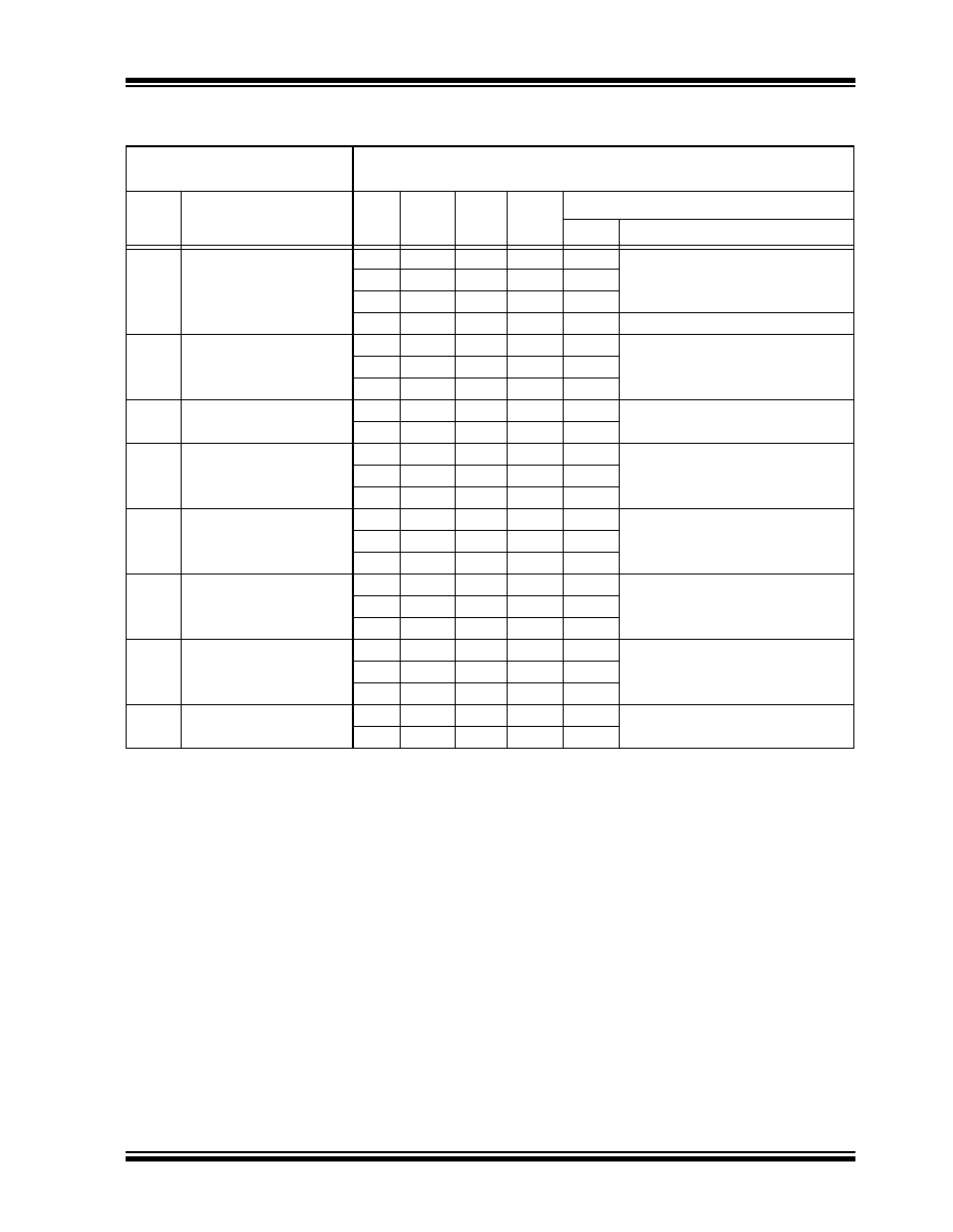
DC Characteristics: PIC12F683-I (Industrial)
DC CHARACTERISTICS
Standard Operating Conditions (unless otherwise stated)
Operating temperature
-40°C
≤ TA ≤ +85°C for industrial
Param
No.
Device Characteristics
Min
Typ
Max
Units
Conditions
VDD
Note
D020
Power-down Base
Current(IPD)(2)
—
0.05
1.2
μA
2.0
WDT, BOR, Comparators, VREF and
T1OSC disabled
—
0.15
1.5
μA3.0
—
0.35
1.8
μA5.0
—
150
500
nA
3.0
-40°C
≤ TA ≤ +25°C
D021
—
1.0
2.2
μA
2.0
WDT Current(1)
—2.0
4.0
μA3.0
—3.0
7.0
μA5.0
D022
—
42
60
μA
3.0
BOR Current(1)
—
85
122
μA5.0
D023
—
32
45
μA
2.0
Comparator Current(1), both
comparators enabled
—60
78
μA3.0
—
120
160
μA5.0
D024
—
30
36
μA2.0
CVREF Current(1) (high range)
—45
55
μA3.0
—75
95
μA5.0
D025*
—
39
47
μA2.0
CVREF Current(1) (low range)
—59
72
μA3.0
—
98
124
μA5.0
D026
—
4.5
7.0
μA
2.0
T1OSC Current(1), 32.768 kHz
—5.0
8.0
μA3.0
—6.0
12
μA5.0
D027
—
0.30
1.6
μA
3.0
A/D Current(1), no conversion in
progress
—
0.36
1.9
μA5.0
*
These parameters are characterized but not tested.
Data in “Typ” column is at 5.0V, 25°C unless otherwise stated. These parameters are for design guidance
only and are not tested.
Note 1:
The peripheral current is the sum of the base IDD or IPD and the additional current consumed when this
peripheral is enabled. The peripheral
Δ current can be determined by subtracting the base IDD or IPD
current from this limit. Max values should be used when calculating total current consumption.
2:
The power-down current in Sleep mode does not depend on the oscillator type. Power-down current is
measured with the part in Sleep mode, with all I/O pins in high-impedance state and tied to VDD.
发布紧急采购,3分钟左右您将得到回复。
相关PDF资料
XF2L-2125-1
CONN FPC 21POS 0.5MM SMT
XF2L-2035-1
CONN FPC 20POS 0.5MM SMT
PIC18F8621T-I/PT
IC PIC MCU FLASH 32KX16 80TQFP
XF2L-1835-1
CONN FPC 18POS 0.5MM SMT
XF2L-1535-1
CONN FPC 15POS 0.5MM SMT
PIC16LF767T-I/SO
IC PIC MCU FLASH 8KX14 28SOIC
XF2L-1335-1
CONN FPC 13POS 0.5MM SMT
XF2L-1325-1
CONN FPC 13POS 0.5MM SMT
相关代理商/技术参数
PIC12F683-I/MDQTP
制造商:MICROCHIP 制造商全称:Microchip Technology 功能描述:8-Pin Flash-Based, 8-Bit CMOS Microcontrollers with nanoWatt Technology
PIC12F683-I/MF
功能描述:8位微控制器 -MCU 3.5KB 128 RAM 6 I/O RoHS:否 制造商:Silicon Labs 核心:8051 处理器系列:C8051F39x 数据总线宽度:8 bit 最大时钟频率:50 MHz 程序存储器大小:16 KB 数据 RAM 大小:1 KB 片上 ADC:Yes 工作电源电压:1.8 V to 3.6 V 工作温度范围:- 40 C to + 105 C 封装 / 箱体:QFN-20 安装风格:SMD/SMT
PIC12F683-I/MF
制造商:Microchip Technology Inc 功能描述:8BIT FLASH MCU SMD 12F683 DFN-8
PIC12F683-I/MFQTP
制造商:MICROCHIP 制造商全称:Microchip Technology 功能描述:8-Pin Flash-Based, 8-Bit CMOS Microcontrollers with nanoWatt Technology
PIC12F683-I/P
功能描述:8位微控制器 -MCU 3.5KB 128 RAM 6 I/O RoHS:否 制造商:Silicon Labs 核心:8051 处理器系列:C8051F39x 数据总线宽度:8 bit 最大时钟频率:50 MHz 程序存储器大小:16 KB 数据 RAM 大小:1 KB 片上 ADC:Yes 工作电源电压:1.8 V to 3.6 V 工作温度范围:- 40 C to + 105 C 封装 / 箱体:QFN-20 安装风格:SMD/SMT
PIC12F683-I/P
制造商:Microchip Technology Inc 功能描述:IC 8BIT FLASH MCU 12F683 DIP8
PIC12F683-I/PQTP
制造商:MICROCHIP 制造商全称:Microchip Technology 功能描述:8-Pin Flash-Based, 8-Bit CMOS Microcontrollers with nanoWatt Technology
PIC12F683-I/SN
功能描述:8位微控制器 -MCU 3.5KB 128 RAM 6 I/O RoHS:否 制造商:Silicon Labs 核心:8051 处理器系列:C8051F39x 数据总线宽度:8 bit 最大时钟频率:50 MHz 程序存储器大小:16 KB 数据 RAM 大小:1 KB 片上 ADC:Yes 工作电源电压:1.8 V to 3.6 V 工作温度范围:- 40 C to + 105 C 封装 / 箱体:QFN-20 安装风格:SMD/SMT